
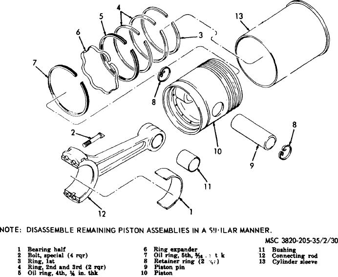
Figure 30. Piston, sleeve, and connecting rod assembly, exploded view.
the sleeve should require a 5 to 10
98.
Piston and Connecting Rod
Assemblies
pound force to pull two 0.004 in.
Cleaning, Inspection, and Repair
feeler gages from between the piston
Cleaning. Clean all parts with an approved
a.
and sleeve. Replace a piston that
cleaning solvent and blow dry with compressed air.
does not meet these standards.
b.
Inspection and Repair.
(4)
Measure the piston pin bore with an
inside micrometer.
The proper
(1)
Use a grooved cleaning tool and
diameter is 1.7498 to 1.7500 inch. If
clean the carbon and varnish out of
the piston pin bore is worn larger than
the ring grooves in the piston.
1.7502 in., replace the piston.
(2)
Clean the oil holes in the connecting
(5)
Roll each piston ring completely
rods and pistons with compressed air.
around in its respective groove in the
(3)
Inspect each piston for cracks,
piston. The fit must be free around
breaks, scoring or other damage.
the entire piston circumference. If the
Measure the cylinder sleeve bore with
rings are tight, they can be lapped
an inside micrometer. The proper
slightly with a very fine emery cloth
distance is 5.5625 to 5.5645 inches.
laid-on a flat surface using a light,
Place the piston in an inverted
uniform pressure.
position about two inches down in the
cylinder sleeve bore. The piston fit in
AGO 3456A
63