
TM 5-3820-233-12/1
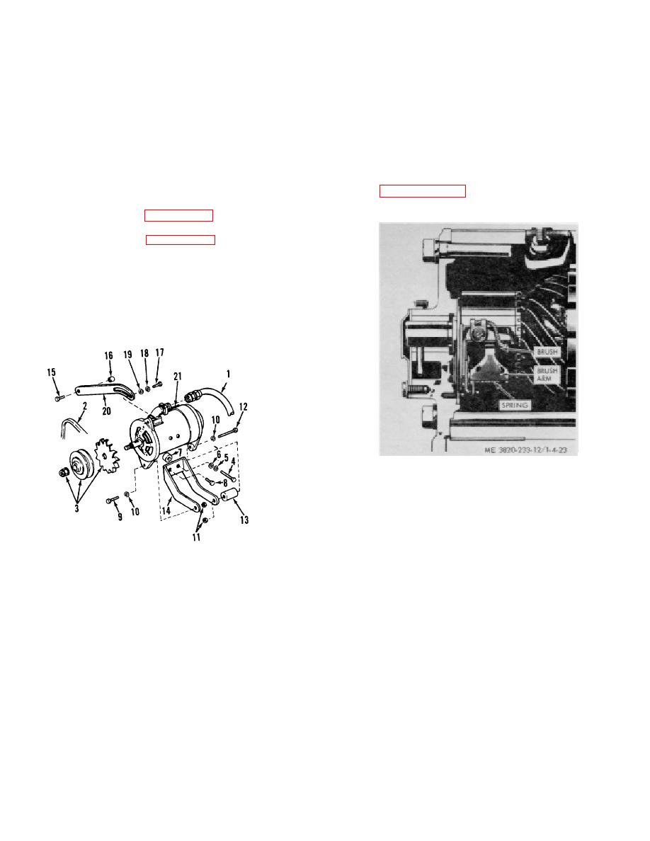
(2) Remove brush terminal screw, life brush arm
4-36. Electrical System
and remove brush. Repeat for other brushes. (3)
Lift
a. The DC battery-charging circuits consist of a
brush arm and install new brush. Secure lead with
generator, reguator, battery and wiring. Refer to figure 1-
screw.
Repeat for other brushes, always replace
3 for wiring diagram. These components functioning
complete set.
together produce electricity for the electrical equipment
(4) Seat brushes using a seating hone or No. 00
on the machine, except for the marker lamps which use
sandpaper.
truck power to operate. In the event of failure or
(5) Position cover band and tighten screw.
improper operation it is essential to check the entire
CAUTION
electrical system. A defect in one component can cause
damage to an- other.
Polarize generator as instructed in
4-37. Generator
a. Removal.
gine.
(1) Refer to figure 3-3A and remove the
generator fan belts.
(2) Refer to figure 4-22 and remove the
generator.
b. Inspection.
(1) Inspect for cracked or broken housing.
(2) Inspect electrical receptacle connector and
bow for cracked or broken position.
(3) Check brushes for excessive wear.
c. Installation. Install generator in reverse order
removal.
Figure 4-23. Generator brush replacement.
4-38. Generator Regulator
a. General.
(1) The generator regulator is a water-tight, dust
proof, fungus and corrosion resistant unit. This unit is
used only with generators having an externally ground
ME 3820-233-12/1-4-22
field circuit.
(2) The three unit regulator consists of a cut out
1. Cable
12. Bolt proof,
voltage regulator and a current regulator in a single
2. V-belt
13. Spacer is use
3. Fan and pulley assembly
14. Bracket
assembly.
4. Bolt
15. Bolt (2
(3) The cut out relay is designed to close the
5. Lockwasher
16. Spacer relay,
circuit from the generator to the battery when generator
6. Washer
17. Bolt
voltage is sufficient to charge the battery, and to open
7. Spacer
18. Lockwasher mount
8. Bolt
19. Washer (3
the circuit when the generator slows or
9. Bolt
20. Strap circuit
(4) The voltage regulator is a limiting device
10. Lockwasher
21. Generator
which prevents the generator voltage from exceeding a
11. Nut
predetermined maximum. With voltage limited, the
generator supplies varying amounts of current to meet
Figure 4-22. Generator, removal and installation.
the requirements of varying states of battery charge and
electrical loads.
d. Generator Brush Replacement.
(1) Loosen screw and slide cover band forward.
4-25
