
TM 5-3820-233-12/1
sandpaper.
4-41. Starting Motor
(5) Position cover band and tighten scews.
a. General. The heavy duty starting motor has a
shift lever and solenoid plunger totally enclosed to
protect from exposure to dirt, icing conditions and splash.
It is located on the lower left side of the engine mounted
on the flywheel housing.
b. Removal. Refer to figure 4-26 and remove the
starting motor.
c. Inspection.
(1) Inspect starter motor solenoid for visual
defects. Replace if defective.
(2) Inspect housing for cracks and inspect gear
for cracks or chipped teeth. Replace starter if defective.
(3) Inspect all wiring for fraying wires or broken
connections. Replace if necessary.
(4) Test all control switches, connecting a
jumper lead around any switch suspected of being
defective. If system functions properly using this method,
repair or replace switch.
(5) Check brushes and replace if required.
d. Installation. Install the starter motor in reverse
order of removal.
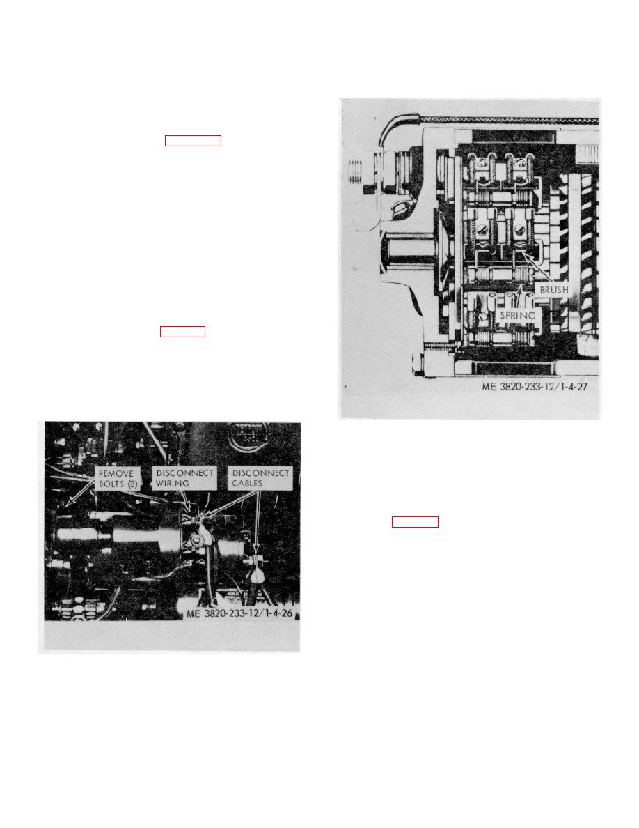
e. Brush Replacement (fig. 4-27).
(1) Remove cover band from starter.
(2) Remove terminal screw, lift brush spring and
remove brush. Repeat for other brushes.
(3) Lift brush spring and install new brush.
Secure lead with terminal screw. Repeat for other
brushes. Always replace complete set.
Figure 4-27. Startling motor, brush replacement.
4-42. Slave Receptacle Connector
a. General. The slave receptacle is mounted on
right front end of the engine below the radiator.
b. Removal.
(1) Disconnect leads of slave receptacle
connectors (fig. 4-28).
(2) Remove four cap screws, nut and lock
washers securing slave receptacle connector to support
and remove connector.
c. Inspection.
(1) Inspect receptacle connector for cracked or
broken condition.
(2) Inspect leads for frayed, cut or broken
insulation. Inspect terminals for corrosion. Replace or
repair broken or damaged parts.
d. Installation.
Install in reverse procedure of
removal.
Figure 4-26. Starting motor, removal and installation
(4) Seat brushes using a seating hone or No. 00
4-28
