
TM 5-3820-233-12/2
f. Timing Fuel Injectors.
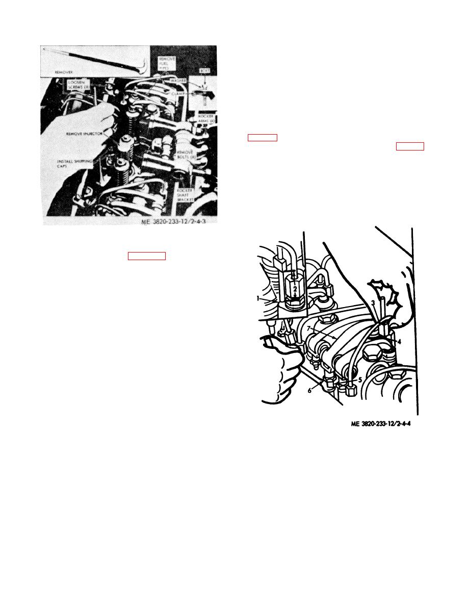
(1) To time an injector properly the injector follower
must be adjusted to a definite height in relation to the
injector body. (use injector time gage No. J1853 FSN
5220-387-9581).
(a) Place the governor control lever in the "NO-
FUEL" position.
(b) Rotate the crankshaft until the exhaust
valves are fully depressed on the cylinder to be timed.
(c) Place small end of the injector timing gage
(3, fig. 4-4) in the hole provided in the top of the injector
body, with flat of gage toward injector follower (fig. 4-4).
(d) Loosen push rod lock nut (6), turn push rod
(5), and adjust the injector rocker arm until extended part of
gage will just pass over top of injector follower (4).
(e) Hold push rod and tighten the lock nut (6).
Check adjustment and readjust the push rod if necessary.
(2) Time the remaining injectors in the same
manner as outlined above. Injectors should be timed in
firing order sequence.
Figure 4-3. Fuel injector, removal and installation.
e. Installation. Refer to figure 4-3 and install the fuel
injector as follows:
(1) Insert the injector into injector tube with dowel
positioned with the locating hole in the cylinder head.
(2) Slide rack control lever over so that it registers
with the injector rack.
(3) Place injector clamp in place and install special
washer. Install bolt and tighten to 20-25 lb. ft. torque.
NOTE
Check the injector control rack for free
movement. Excess torque can cause the control
rack to stick or bind.
(4) Move the rocker arm assembly into position and
tighten rocker arm bracket bolts to 90-1000 lb. ft. torque.
(5) Remove shipping caps, install and connect fuel
pipes. Tighten connections to 12-50 lb. ft. torque.
CAUTION
Do not bend the fuel pipes or exceed specified
torque.
Excessive tightening will twist or
fracture fuel lines, causing leaks. Lubricating
oil diluted by fuel oil can cause serious damage
1.
Fuel injector
2.
Timing dimension
to engine bearings.
3.
Timing gage No. J1853
(6) Replacement of one injector does not warrant a
4.
Injector follower
complete engine tune-up. When in- stalling one injector
5.
Push rod
follow instructions outlined below.
6.
Locknut
(a) Adjust the exhaust valve clearance.
7.
Rocker arm
(b) Time the injector.
(c) Position injector control rack levers.
Figure 4-4. Timing fuel injectors.
4-6
