TM 5-3820-233-12/2
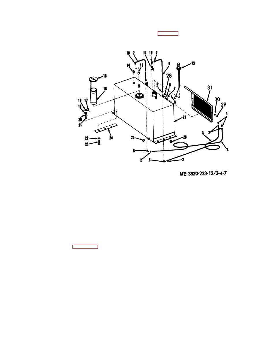
c. Installation. Install the fuel tank, lines and fittings as
leaks. Replace defective parts or a defective tank.
illustrated in figure 4-7.
1. Coupling
2. Nut
3. Feed tube
4. Return tube
5. Elbow
6. Bolt
7. Clamp
8. Clamp base
9. Tube
10. Elbow
11. Shut-off Valve
12. Bushing
13. Fuel Gage
14. Air vent
15. Filler tube
16. Filler cap
17. Cotter pin
18. Nut
19. Washer
20. Washer
21. Bushing
22. Washer
23. Capscrew
24. Fuel tank pad
25. Draincock
26. Plug
27. Fuel tank
28. Capscrew
29. Nut
Figure 4-7. Fuel tank, lines and fittings, removal and installation.
30. Lockwasher
31. Guard
(2) Remove bolt (2).
4-17. Starting Aid
(3) Remove mounting bracket and discharge
a. General. The starting aid is mounted to the top of
assembly.
the hood support assembly. The discharger is designed to
(4) Remove chamber base from mounting bracket.
inject a highly volatile fluid into the air intake system to
CAUTION
assist ignition of fuel at low ambient temperature. The fluid
is contained in suitable capsules (FSN 2910-355-6377) to
Keep starting capsules away from heat. Insert;
facilitate handling.
capsules in discharger at time of starting only.
b. Removal. Refer to figure 4-8 and remove the
c. Installation. Installation is the reverse procedure of
starting aid as follows.
removal.
(1) Loosen nut and remove discharge line.
4-10


