
TM 5-3820-233-12/2
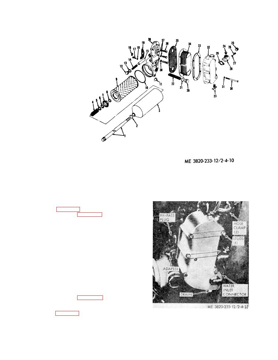
1. Stud
2. Washer
3. Shell
4. Spring
5. Gasket
6. Gasket
7. Retainer
8. Nut
9. Element
10. Gasket
11. Plug
12. Plug
13. Gasket
14. Spring
15. Valve
16. Gasket
17. Bolt
18. Lockwasher
19. Gasket
20. Plug
21. Gasket
22. Spring
23. Drain cock
24. Plug
25. Plug
26. Capscrew
27. Lockwasher
28. Flange
29. Gasket
30. Bolt
31. Lockwasher
32. Housing
33. Gasket
34. Core
35. Gasket
36. Bolt
Figure 4-10. Full-flow Lubricating oil filter and oil cooler, disassembly and reassenbly.
37. Lockwasher
38. Washer
39. Adapter
(2) Fill the cooling system to the proper
4-21. Oil Cooler
level.
a. Removal.
(1) Drain the cooling system.
(2) Refer to figure 4-11 and remove the oil cooler.
b. Disassembly. Refer to figure 4-10 and disassemble
the oil cooler.
c. Inspection. Inspect all parts for cracks, breaks and
damage.
d. Test. The oil cooler core may be checked for leaks
as follows:
(1) Make a suitable plate and attach it to the flange
side of the cooler core. Use a gasket made from rubber to
assure a tight seal. The plate should be drilled and tapped
to permit an air hose fitting to be attached at the inlet side
of the core.
(2) Attach an air hose and apply approximately 75
psi air pressure and submerge the cooler core and plate
assembly in a container of water. Any leaks will be
indicated by air bubbles in the water. If leaks are
indicated, replace the core.
e. Reassembly. Refer to figure 4-10 and reassemble
the oil cooler.
f. Installation.
(1) Refer to figure 4-11 and install the oil cooler.
Figure 4-11. Oil cooler, removal and installation.
4-13
