TM 5-3820-233-12/2
4-27. Water Tubes, Hoses and Fittings
a. Removal.
(1) Drain the cooling system.
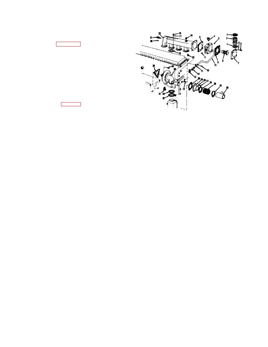
(2) Refer to figure 4-15 and remove the water
tube, hoses and fittings.
b. Inspection.
(1) Inspect the water tubes for cracks or breaks.
(2) Inspect the hoses for deterioration or cuts.
(3) Inspect the fittings for damage. Replace a
defective part.
c. Installation.
(1) Install the water tubes, hoses and fittings in
the reverse procedure of removal.
(2) Fill the cooling system to the proper level.
4-28. Water Pump
The water pump (35, fig. 4-15) is a centrifugal type
pump, mounted on the front end of the blower, driven by
the lower blower rotor shaft. The pump bearing is filled
ME 3820233-12/2-4-15
with lubricant at the time it is assembled to the pump
1. Clamp
13.
Clamp
25. Tube
shaft, and no further lubricant is required.
2. Hose
14.
Hose
26. Hose
3. Plug
15.
Tube assembly
27. Bolt
4. Drain cock
16.
Nut
28. Lockwasher
5. Bolt
17.
Lockwasher
29. Connection
6. Lockwasher
18.
Gasket
30. Gasket
7. Elbow
19.
Plug
31. Drain cock
8. Thermostat
20.
Plug
32. Clamp
9. Gasket
21.
33. Seal
10. Bolt
22.
Manifold
34. Bolt
11. Clamp
23.
Stud
35. Pump assembly
12. Spacer
24.
Clamp
36. Gasket
Figure 4-15. Water tubes, hoses, and fittings, removal and
installation.
4-16


