
TM 5-3820-233-35/1
tension increases the voltage setting. After
venient method of performing this operation
each change of adjustment, reduce generator
is to insert the gage, press the armature down
speed until cutout relay opens; then return
against it to hold it in place, and then turn
the contact screw until the contacts barely
to speed and read voltage.
touch.
(3) Current Regulator. Two checks and
(b) Voltage Setting--(fig. 9-6). Dis-
adjustments are required on the current regu-
connect battery cable from regulator, and con-
lator: air gap and current setting. The AIR
nect voltmeter between regulator battery ter-
GAPand
not
the
POINT
OPENING
is
minal, and ground screws in the end of the
checked and adjusted-procedure being the
regulator. With the generator operating at ap-
same as for the voltage regulator above. Cur-
proximately 3000 RPM and the regulator at
rent Setting (fig. 9-7). To check the current
operating temperature, note the voltage set-
regulator setting, it is necessary to keep the
ting. Adjust by turning the adjusting screw
voltage regulator from operating so that the
at the base of the unit, thereby changing the
generator output can increase to the value for
spiral spring tension. Increasing the spring
which the current regulator is adjusted, and
thus cause the current regulator to operate.
Three methods of preventing voltage regu-
lator operation are available. Regardless of the
method used, disconnect battery cable from
the regulator and connect an accurate am-
meter in series between these junctions. This
meter will measure the current regulator
setting. The three methods of preventing
voltage
regulator
operation
are:
Method--By
(a) Battery Discharge
this method, the battery is partly discharged
by cranking the engine for 30 seconds with
lights,
and other accessories turned on.
NEVER USE THE CRANKING MOTOR
FOR MORE THAN 30 SECONDS AT A
TIME WITHOUT PAUSING TO ALLOW
THE CRANKING MOTOR TO COOL OFF.
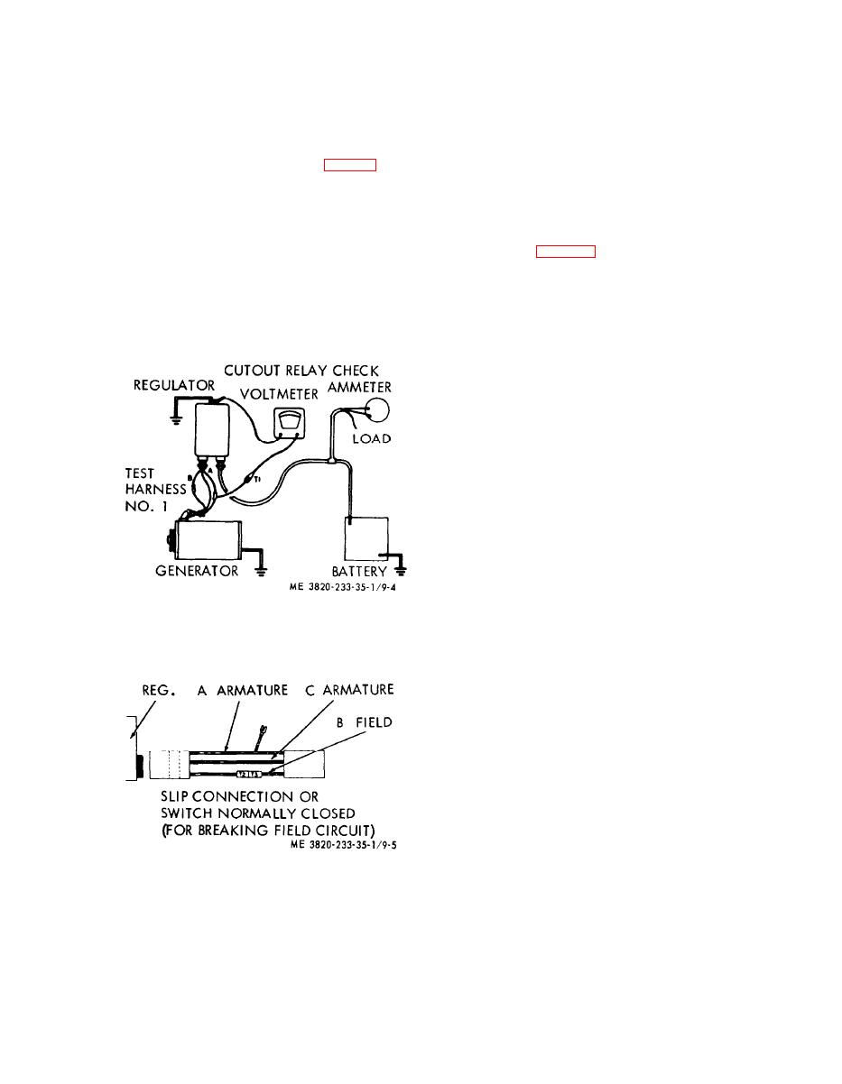
Figure 9-4. Meter connections for checking cutout
Excessive cranking will damage the cranking
relay closing voltage.
motor. Immediately after the cranking cycle,
start the engine and allow the generator out-
put to increase to its maximum as determined
by the current regulator setting before rising
battery voltage causes the voltage regulator
to operate. Since battery voltage recovers
very quickly, this method requires prompt
action.
(b) Load Method--If a load approxi-
mating the current regulator setting is placed
across the battery during the time that the
current regulator setting test is made, the
voltage will not increase sufficiently to cause
the voltage regulator to operate. This load
may be provided by a carbon pile or other
suitable resistance.
for electrical checking.
3-9
