TM 5-3820-233-35/1
Caution. Keep solvent away from non-
the speed is reduced approximately 100 rpm
below the trip speed of 1500 rpm.
metallic portions of electrical components.
(2) Inspect the terminals and contacts
b. Removal and Installation. Refer to the
on the trip governor switch.
Operator's Manual.
(3) Visually inspect all parts for de-
c. Gleaning, Inspection, and Repair
fects. Replace a defective part.
d. Assembly and Disassembly. Refer to
(1) Clean disassembled metal parts in
an approved cleaning solvent and dry
thoroughly.
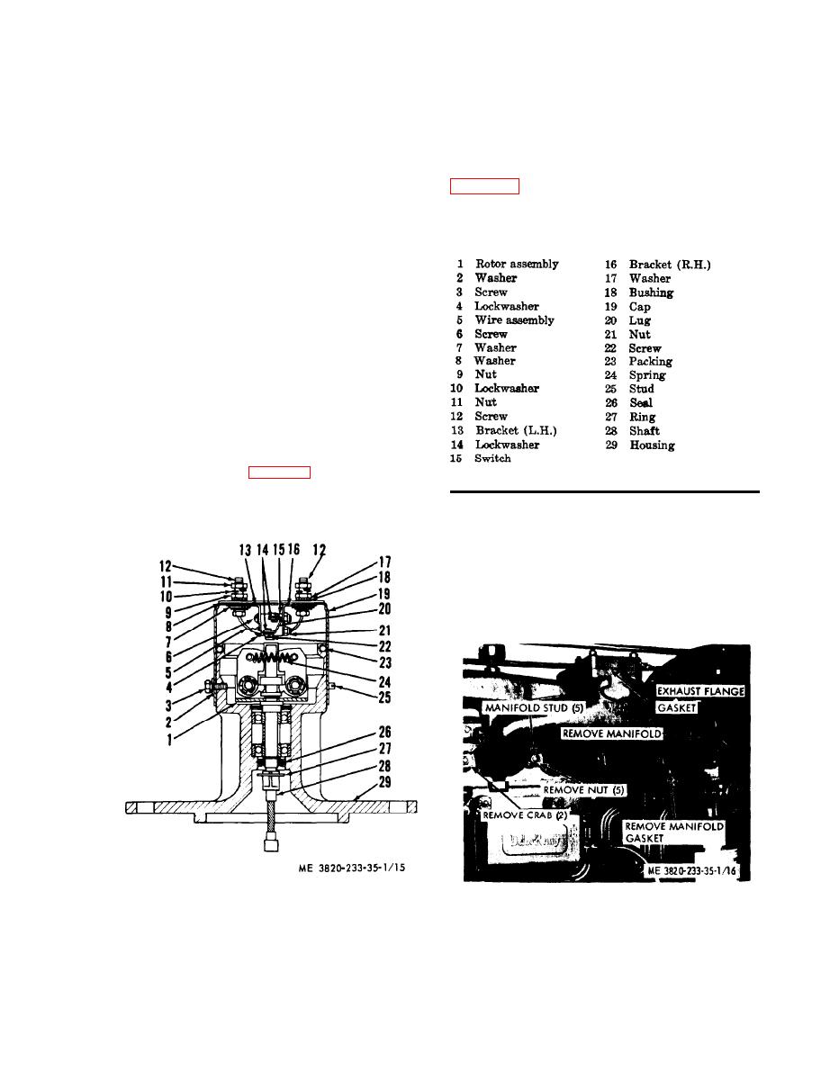
overspeed governor.
Section II. ENGlNE COMPONENTS
38. General
The engine is a four cylinder, two cycle,
diesel with overhead valves. The engine com-
ponents are fully described in the applicable
paragraphs throughout this section.
39. Exhaust Manifold
a. General. The air cooled exhaust mani-
fold is mounted on the cylinder head.
b. Removal
(1) Disconnect the muffler from the ex-
haust manifold.
(2) Refer to figure 16 and remove the
Figure 15 --Continued.
exhaust manifold.
c. Cleaning and Inspection
(1) Remove loose carbon deposits and
other foreign material from the internal walls
of the exhaust manifold.
(2) Inspect exhaust manifold studs for
damage. If stud threads are stripped, replace
Figure 15. Overspeed governor, disassembly and
Figure 16. Exhaust manifold, removal and installation.
reassembly.


