
TM 5-3820-233-35/1
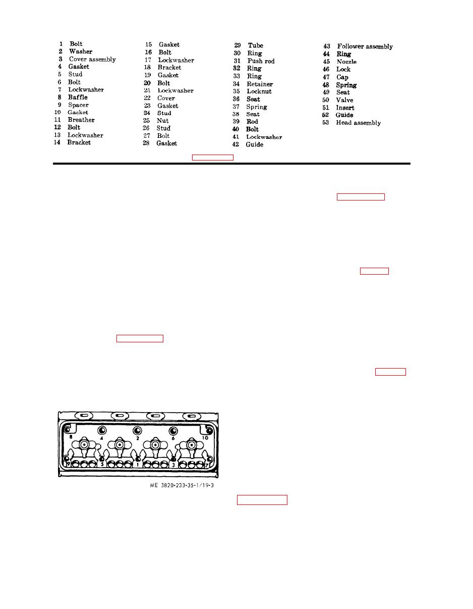
Figure 19-2-Continued.
The rings above the pin are compression
c. Disassembly. Disassemble the piston and
rings which form an airtight seal between the
connecting rod assemblies in the numerical
pistons and cylinder liners. The rings below
sequence as illustrated on figure 22-2.
the pin are oil control rings which scrape the
d. Cleaning, inspection, and Repair
excess oil from the cylinder wall.
(1) Clean all parts with an approved
cleaning solvent and dry thoroughly.
b. Removal
(2) Inspect the pistons for wear, cracks,
(1) Drain the engine oil (Operator's
scoring and damage. Replace a defective
Manual).
piston.
(2) Remove the power unit (para 24).
(3) Measure the pistons and bore in the
(3) Remove the muffler and air cleaner
cylinder sleeves for clearance (table 1). Re-
(Operator's Manual).
place defective parts.
(4) Remove the hoods, side panels, and
(4) Inspect the piston rings for fit in the
tie rods (Operator's Manual).
grooves, clearance, and wear. Refer to table
(5) Remove the cylinder head (para 42).
1 for tolerances. Replace defective piston
(6) Remove the oil pan (para 43).
rings as necessary.
(7) Remove the lubricating oil pump
(5) Inspect and measure the inside di-
(para 44).
mension of the piston pin bushings for wear
(8) Refer to figure 22-1 and remove the
(table 1). Replace defective bushings as
piston and connecting rod assemblies.
necessary.
Note. Ridge ream carbon deposits from the
(6) Inspect and measure the outside di-
upper inner surface of the cylinder liner before re-
ameter of the piston pin for wear (table 1).
moving the piston and connecting rod assemblies.
Replace a defective piston pin.
(7) Inspect the bearing shells for
scoring, pitting, flaking, chipping, cracking,
or signs of overheating. Inspect the backs of
the bearing shells for bright spots which indi-
cate the bearings have been moving in their
supports. If any of these conditions exist, re-
place the bearing shells.
Note. If either the upper or lower bearing
shell needs replacing, both shells must be replaced.
e. Reassembly. Reassemble the piston and
connecting rod assemblies in the reverse of
the numerical sequence as illustrated on
3-31
