
TM 5-3820-233-35/2
1
Capscrew
15
Capscrew
29
Hopper liner
2
Bevel washer
16
Screen stop
30
Hopper liner
3
Lockwasher
17
Screen stop
31
Partition liner
4
Nut
18
Hopper liner
32
Partition liner
5
Capscrew
19
Hopper liner
83
Gate liner
6
Gate
20
Hopper liner
34
Nut
7
Handle
21
Hopper liner
35
Washer
8
Caper
22
Hopper liner
86
Bolt
9
Lockwasher
23
Hopper liner
37
Liner
10
Nut
24
Hopper liner
38
Hopper liner
11
Arms door
25
Hopper liner
39
Hopper liner
12
Bolt
26
Hopper liner
40
Hopper
13
Lockwasher
27
Door liner
14
Nut
28
Hopper liner
Figure 40-4--Continued
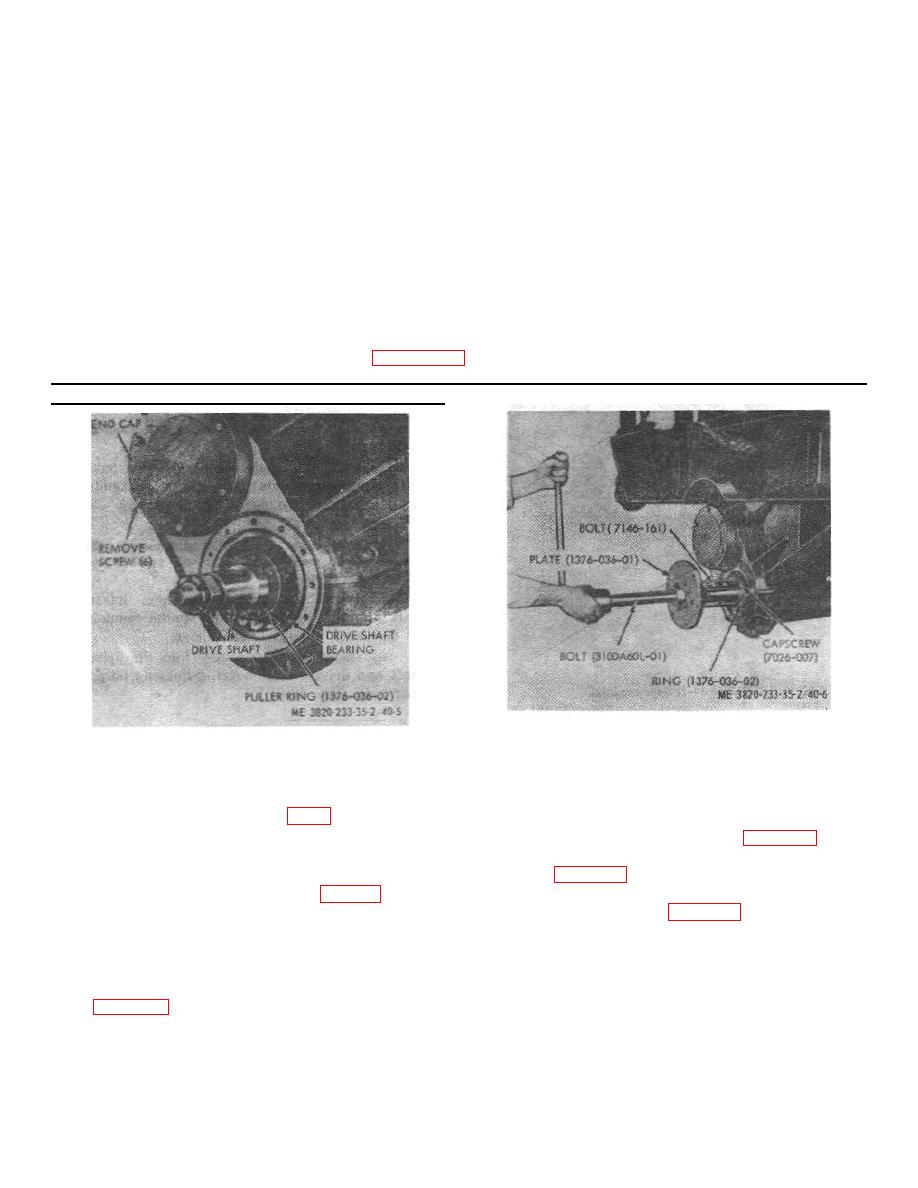
Figure 40-6. Dive shaft bearing removal, drive side.
Figure 40-5. Vibrator unit.
(17) Measure for a minimum 0.010 inch
and inner rotating seals in a similar manner as discussed
clearance between the rotating seal and the fixed seal.
in step 68b. above.
(18) Install screen pulley (fig. 8).
(4) Remove bearing spacer from the driver
(19) Refer to the Operator's Manual for vibrator
shaft and driven bearing housing bores (fig. 40-12).
unit bearing and gear lubrication instructions.
(5) Remove the bearing housing and inner
fixed seals (fig. 40-11).
(6) Use a suitable lifting device and remove
the driver and driven shafts (fig. 40-13).
e. Vibrator Unit Disassembly.
f. Cleaning, Inspection, and Repair.
(1) Remove the drive shaft and driven shaft
bearings (drive side) and inner rotating seals in a similar
(1) Clean all parts with an approved cleaning
manner as discussed in step 68a. above.
solvent, and dry thoroughly.
(2) Remove bearing housing and inner fixed
seals (fig. 40-11).
4-33
