TESTING AND ADJUSTMENT
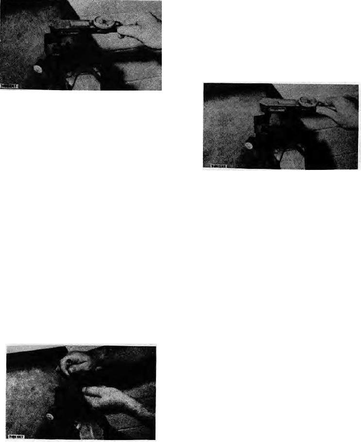
3. Turn the lift adjustment screw (6) counterclockwise 3/4
1/8 of a turn.
4. Hold the lift adjustment screw (6) with a screwdriver and
tighten locknut (5) just enough so that the lift adjustment
screw (6) will not turn.
5. Put the fuel injection nozzle in the 882250 Nozzle
Holding Tool. Put the 8S2250 Nozzle Holding Tool in a
vise and tighten locknut (5) to 356 to 40 lb. in. (40.4 to
46.1 cm. kg).
TIGHTENING PRESSURE SCREW
f.
Remove the fuel injection nozzle from the 882250
Nozzle Holding Tool. Connect the fuel injection
nozzle, to the 8S2267 Nozzle Tester. Make sure
the tip of the fuel injection nozzle is in the down
position. Point the tip of the fuel injection nozzle
into the 862270 Fuel Collector. Check the opening
pressure. If the opening pressure is not correct, do
TIGHTENING LOCKNUT
the complete procedure in Step 3 again.
Checking Seat Condition
Valve Lift Adjustment
1. Put a shop towel around the top of the body of the fuel
injection nozzle (pressure screw end) to take in the
1. With the opening pressure correct and while pumping
leakage. Close the gauge protector valve.
test oil through the fuel injection nozzle, hold the
2. Point the tip of the fuel injection nozzle into the 8S2270
locknut (5) and slowly turn the lift adjustment screw (6)
Fuel Collector and operate the pump rapidly for a
clockwise until no fuel comes from the fuel injection
minimum of five strokes to put the valve on the seat.
nozzle.
Open the gauge protector valve. Be sure the nozzle tip
is completely dry.
2. Check to be sure the valve is on the seat by making
the pressure 200 to 500 psi (14.06 to 83.15 kg/cm2)
3. Make the pressure 250 to 800 psi (17.6 to 21.1 kg/cm )
more than the opening pressure.
less than the opening pressure. If more than 3 drops of
fuel get on the tip of the fuel injection nozzle in 15
CAUTION: Do not bend the valve or damage the seat by
seconds, clean or make replacement to the fuel
turning the lift adjustment screw (6) with too much force.
injection nozzle.
NOTE: Some fuel can be at the tip of the fuel injection
Spray Characteristic (Pattern)
nozzle but a rapid flow of drops (dribble) must not be seen.
NOTE: The adjustment for the valve lift must be correct
before checking the spray pattern.
1. Close the gauge protector valve and the on-off valve.
Open the pump isolator valve.
2. Point the tip of the fuel injection nozzle into the 8S2270
Fuel Collector.
3. Make a slow increase in pressure and look at the spray
pattern when fluid begins to flow through the fuel
injection nozzle. The spray must be the same through
all four orifices.
Any change, either vertically or
horizontally, is an indication of a bad nozzle. See the
TIGHTENING LOCKNUT
ANALYSIS OF NOZZLE SPRAY PATTERN.
52

