
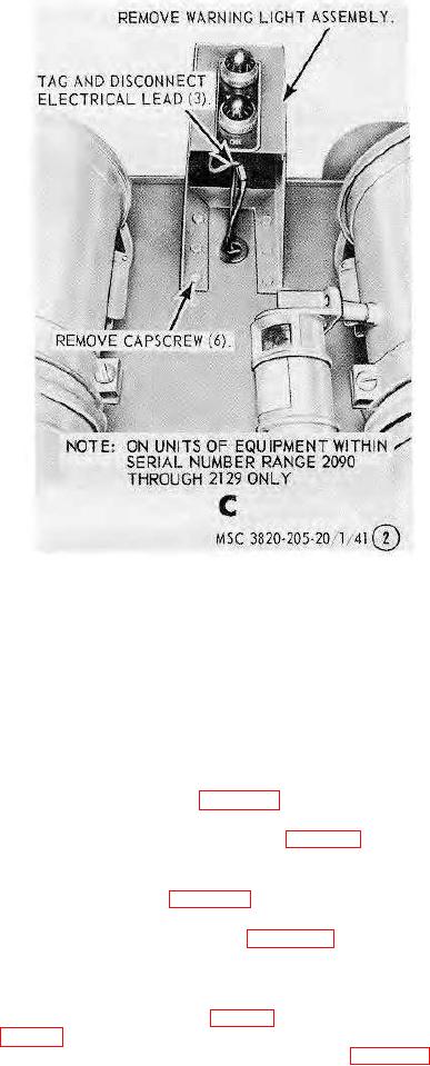
C--Low oil pressure and high water temperature warning lights (on units of equipment within serial No. Range 2090
through 2129 only)
Figure 42--Continued.
Section VI. ENGINE HOUSING
94.
General
The engine housing is constructed of pre-formed sheet metal and includes the doors, door supports, side panels,
hood, radiator cowling, rear panel, and necessary attaching hardware to construct the housing.
95.
Water Drain Lines
a. Removal. Remove the drain lines as instructed on figure 43.
b. Cleaning and Inspection. Clean and inspect all lines and replace as necessary.
c. Installation. Install the drain lines in reverse of instructions on figure 43.
96.
Doors
a. Removal. Remove the doors as instructed on figure 44.
b. Cleaning, Inspection, and Repair. Clean and inspect the doors for any damage. Repair or replace if necessary.
c. Installation. Install the doors in reverse of instructions on figure 44. -
97.
Engine Door Supports and Side Panels
a. Removal.
(1) Remove the crankcase and water drain lines (par. 95).
(2) Remove the doors (par. 96).
(3) Remove the engine door supports and side panels as instructed on figure 45.
b. Cleaning and Inspection. Clean the engine door supports and side panels. Inspect for any damage and replace
as necessary.
AGO 8166A
62