
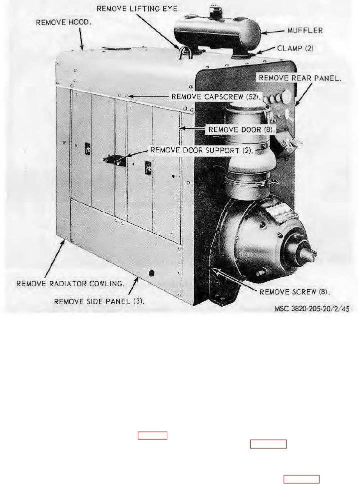
Figure 45. Engine housing removal and installation.
Section VII. VALVE COVER AND ROCKER ARM ASSEMBLY
99. General
The engine intake and exhaust valves are located in the cylinder heads. There are three intake and three
exhaust valves, rocker arms, and rocker arms adjusting screws located under each valve cover. The valve
covers and breather must be removed to perform rocker arm adjustment.
100. Valve Covers and Breather
a.
Removal
(1)
Remove the engine hood (par. 98).
(2)
Remove the two valve covers and breather as instructed on figure 46.
b.
Cleaning and Inspection. Clean and inspect all parts. Replace gaskets and damaged parts.
c.
Installation.
(1)
Install the two valve covers and breather in reverse of instructions on figure 46.
(2)
Install the engine hood (par.98)
65