
174.
Slack Adjusters
a. Removal.
(1) Disconnect linkage from air brake chamber (par. 139).
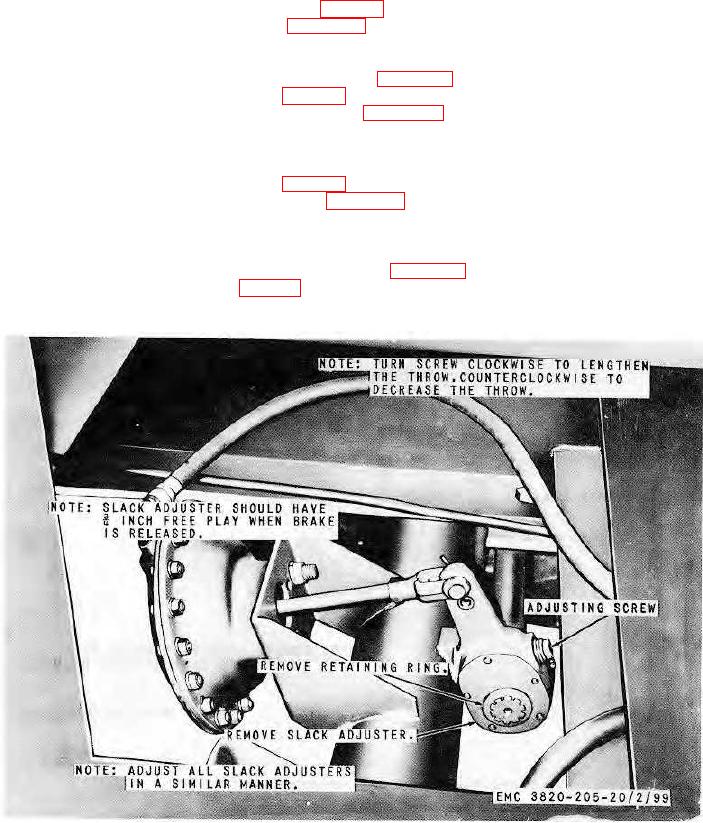
(2) Remove slack adjuster as instructed on figure 104.
b. Cleaning and Inspection. Clean and inspect all parts. Replace all damaged or defective parts.
c. Installation.
(1) Install the slack adjuster in reverse of instructions on figure 104.
(2) Connect linkage to air brake chamber (par. 139).
d. Adjustment. Adjust the slack adjusters as instructed on figure 104.
175.
Brake Assembly
a. Removal.
(1) Remove the wheel and hub assembly (par. 116).
(2) Remove the brake assembly as instructed on figure 105.
b. Cleaning, Inspection, and Repair. Clean and inspect all parts. Replace or repair all damaged or defective or
worn parts.
c. Installation.
(1) Install the brake assembly in reverse of instructions on figure 105.
(2) Install the wheel hub assembly (par. 116).
d. Adjustment. Adjust the slack adjusters (par. 174).
Figure 104. Slack adjuster removal, installation, and adjustment.
AGO 8156A
135