
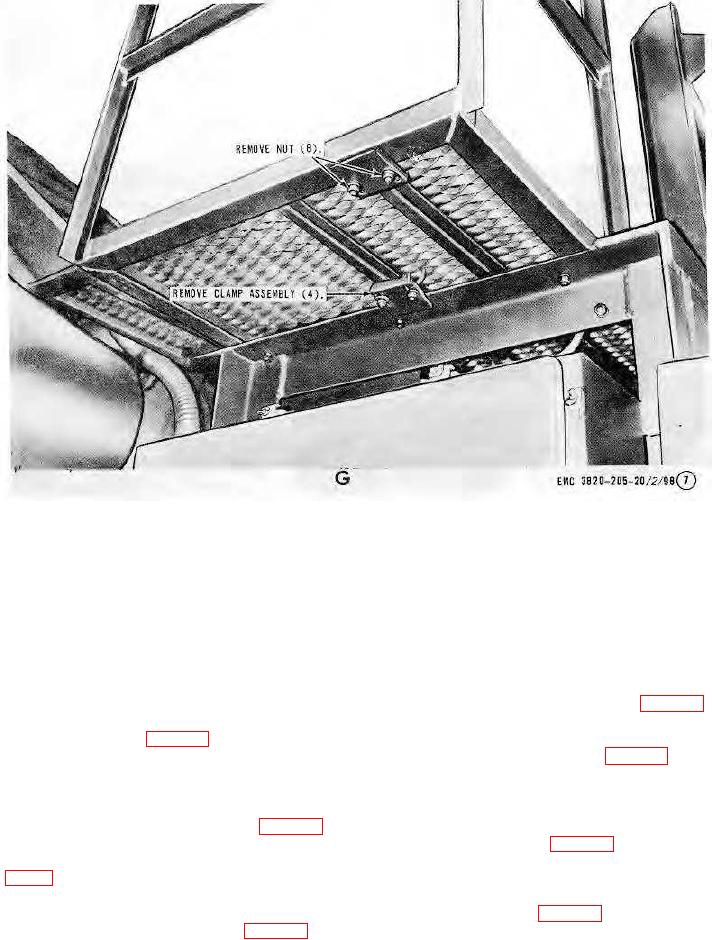
G-Lower platform ladder installed view.
Figure 103-Continued.
Section IX. REAR WHEELS, TIRES, AND BRAKE ASSEMBLY
171.
General
The rear wheels, tires, and brake assembly consists of wheels, tires, hub, slack adjusters, and brake assembly. The
wheels are dual-type and separated by a spacer. The assembly is secured to the hub and brakedrum.
172.
Rear Wheels and Tires
a. Removal. Remove the rear wheels and tires in the same manner as the dolly wheels and tires (par. 115a).
b. Cleaning, Inspection, and Repair. Clean and inspect, replace or repair the tires and wheels in the same manner
as the dolly wheels and tires (par. 115b).
c. Installation. Install the wheels and tires in the same manner as the dolly wheels and tires (par. 115a).
173.
Rear Wheel Hub Assembly and Brakedrum
a. Removal.
(1) Remove the rear wheel assembly (par. 172).
(2) Remove and disassemble the wheel bearings, hub, and brakedrum assembly (par. 116).
b. Cleaning and Inspection. Clean and inspect all parts. Replace all damaged or defective parts. Lubricate wheel
bearing (par. 1'6).
c. Installation.
(1) Reassemble and install the brake-drum, wheel hub, and bearings assembly (par. 116).
(2) Install the rear wheel assembly (par. 172).
AGO 8156A
134