
27. Air Brakes Fail To Operate
Possible remedy
Probable cause
Air relay valve defective---------------------------------Repair or replace air relay valve (pars. 228-230).
Air chambers dcfective------------------------------------Repair or replace air chambers (pars. 231-233).
Section III. REMOVAL AND INSTALLATION OF MAJOR COMPONENTS
OR AUXILIARIES
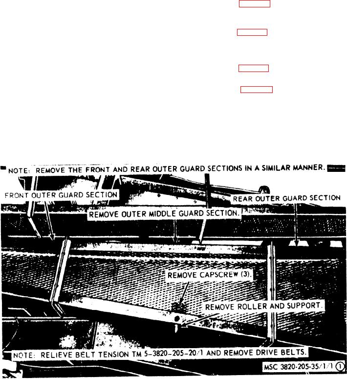
(3) Refer to figure 1, and remove the drive
28. General
belt guards and supports from the
This section provides the necessary informa-
unit.
tion to field and depot. maintenance personnel
(4) Refer to figure 2, and remove the en-
for removal of the engine, reciprocating feeder,
g i n e from the unit.
feeder conveyor, rotary elevator, under con-
v e y o r , vibrator screen, roll crusher assembly,
b. Installation.
and bogie and rear axle assembly from the
(1) Refer to figure 2, and install the en-
E a g l e Roll Crusher Model 5230B.
gine on the unit.
(2) Refer to figure 1, and install the drive
29. Engine Assembly
belt guards and supports on the unit.
a . Removal.
( 3 ) Install the fuel supply lines (TM 5-
(1) Disconnect the battery lead from the
3820-205-20/1).
engine (TM 5-3820-205-20/1).
( 4 ) Install the battery leads (TM 5-3820-
(2) Disconnect the fuel supply lines from
205-20/1).
t h e engine (TM 5-3820-205-20/1).
F i g u r e 1. Drive belt guard and supports, removal and insatllation.
AGO 8498A