
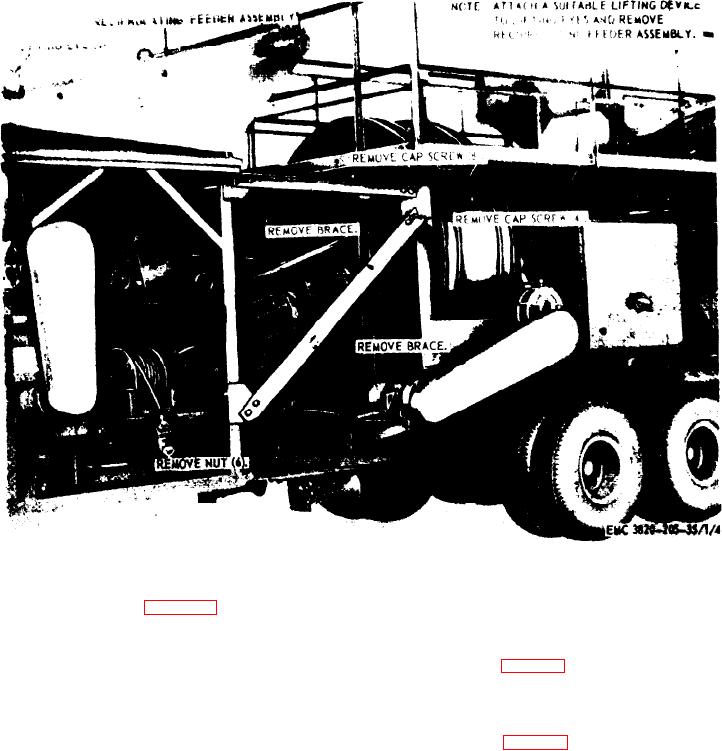
Figure 3. Reciprocating feeder assembly, removal and installation.
( 2 ) Using a suitable lifting device raise
(4) Refer to figure 8, and remove the
and crib the rear portion of the
crusher assembly from the unit.
crusher assembly.
b. lnstallation.
(3) Refer to figure 9, and remove the bogie
(1) Refer to figure 8, and install the
and rear axle assembly from the unit.
crusher assembly on the unit.
b. Installation.
( 2 ) Install the main drive belts (par. 29).
(1) Refer to figure 9, and install the bogie
( 3 ) Install the vibrator screen assembly
and rear axle assembly on the unit.
( p a r . 34).
(2) Using a suitable lifting device lift the
( 4 ) Install the feeder conveyor assembly
r e a r portion of the crusher assembly
( p a r . 31).
and remove the cribbing.
36. Bogie and Rear Axle Assembly
(3) Lower the rear portion of the crusher
assembly.
a. Removal.
(4) Connect the brake airlines (TM 5-
(1) Disconnect the brake airlines (TM 5-
3820-205-20/1).
3820-205-20/1) .
AGO 8498A
24