
187. Tail Section
Conveyor
Hopper
Assembly
b. Install the tail section of the discharge conveyor
Installation
assembly (par. 34).
a. Refer to figure 54 and install the tail section
c. Install the strips and liners (TM 5-3820-205-
conveyor hopper assembly on the unit.
20/2).
Section V. DISCHARGE CONVEYOR HEAD AND TAIL SHAFT PULLEYS
188. General
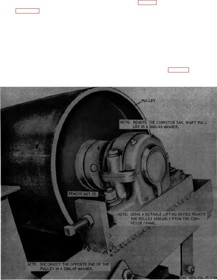
189. Discharge Conveyor Head and Tail Shaft
Pulleys Removal and Disassembly
The head and the tail shaft pulleys are mounted on
the ends of the discharge conveyor frame assembly.
a. Removal.
The purpose of the pulleys is to provide the tension and
(1) Remove the conveyor
gear
reducer
the oscillating power for the conveyor belt, which is
assembly (par. 181).
driven by the head shaft pulley.
Figure 55. Discharge conveyor head and tail shaft pulleys, removal and installation.
AGO 3456A
105