
TM 5-3820-233-12/1
NOTE
Check the injector control rack for free
movement. Excess torque can cause the
control rack to stick or bind.
(4) Move the rocker arm assembly into position and
tighten rocker arm bracket bolts to 90-100 lb-ft. torque.
(5) Remove shipping caps, install and connect fuel
pipes. Tighten connections to 12-50 lb-ft. torque.
(6) Replacement of one injector does not warrant a
complete engine tune-up. When installing one injector
follow instructions outlined below.
(a) Adjust the exhaust valve clearance.
(b) Time the injector.
(c) Position injector control rack levers.
f Timing Fuel injectors.
(1) To time an injector properly the injector follower
must be adjusted to a definite height in relation to the
injector body.
(a) Place the governor control lever in the "NO-
FUEL" position.
(b) Rotate the crankshaft until the exhaust valves
are fully depressed on the cylinder to be timed.
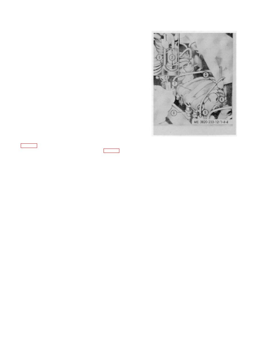
1. Fuel injector
5. Push rod
(c) Place small end of the injector timing gage
2.Timing dimension
6. Locknut
(3, fig. 4-4) in the hole provided in the top of the injector
3. Timing gage
7. Rocker arm
4. Injector follower
body, with flat of gage toward injector follower (fig. 4-4).
(d) Loosen push rod lock nut (6), turn push rod
Figure 4-4. Timing fuel injectors.
(5) and adjust the injector rocker arm until extended part
of gage will just pass over top of injector follower (4).
(6)Make sure the rack remains snug on the pin of
(e) Hold push rod and tighten the lock nut (6).
the rack control lever at number 1 injector.
Check adjustment and readjust the push rod if
(7) Position the remaining rack control levers. When
necessary.
settings are correct, the racks of all injectors must be
(2) Time the remaining injectors in the same manner
snug on the pins of the rack control levers when control
as outlined above. Injectors should be timed in firing
tube lever is in "FULL FUEL" position.
order sequence.
4-14. Exhaust Valve Clearance Adjustment
g. Position the Injector Rack Control Levers.
a. General Whenever the valve operating
(1) Turn outer adjusting screw in until a slight
mechanism is disturbed in any way, the valve clearance
movement of the injector control tube lever is observed.
must first be adjusted to the cold setting to allow for
Tighten inner adjusting screw.
normal expansion of the engine parts during engine
(2) Pull out fuel rod and check for 1/32" to 1/16"
warm-up period. This will ensure a valve setting that is
movement. If movement exceeds this back off inner
close enough to the specified clearance to prevent
adjusting screw 1/8 of a turn and tighten outer adjusting
damage to the valves when the engine is started.
screw. If less than specified back off outer adjusting
b. Adjustment (cold).
screw 1/8 of a turn and tighten inner screw.
NOTE
(3) Disconnect fuel rod from injector control tube
Exhaust valve may be adjusted, in firing order sequence, during
lever.
one full revolution of the crankshaft.
(4) Holding onto clevis at end of injector control tube
(1) Place the governor speed control rod lever in the
position number 1 injector in the FULL FUEL position,
No-Fuel position.
and screw of number 2 injector until the injector control
(2) Rotate the crankshaft until the injector follower is
lever for that injector contacts the injector body.
fully depressed on the cylinder to be adjusted
(5) Tighten outer adjusting screw until it touches
CAUTION
lightly on the injector control tube. Alternately tighten
When using a wrench on the crankshaft
both the inner and outer adjusting screws until tight.
4-7
