
TM 5-3820-233-35/2
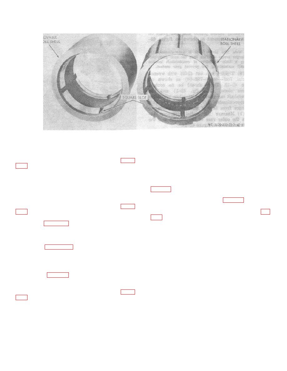
Figure 42-11. Roll shells.
Note
(2) Install the stationary roll shaft and bearing
Compress tension roll springs evenly
assembly to the crusher in the position shown on figure
until an approximately 1/2 inch gap is
obtained between coils.
(3) Aline the stationary roll shaft and bearing
assembly to the crusher frame by installing studs (256)
o. Countershaft Bearing Reassembly.
and nuts (255) (fig. 421).
(1) Assemble bearing adapters (237 and 251,
(4) Assemble the bearing block spacers (121)
next to the stationary bearing blocks (272 and 292).
marks on the adapters with those on the countershaft
housing made during disassembly (fig. 42-9).
(5) Install the movable roll shaft and bearing
assembly to the crusher in the position shown on figure
(2) Secure the bearing adapters to the
countershaft housing with capscrews (237 and 250, fig.
(6) Assemble parts 110 through 120 as
illustrated on figure 42-1.
(3) Install countershaft (252) int o housing.
Install bearing spacer (239), bearing sleeve (238),
n. Tension Roll Spring and Shear Washer
bearing (234), lockwasher (233), and lock nut (232) on
Reassembly.
the countershaft. Do not tighten lock nut (232).
(1) Reverse the disassembly procedure
(4) Center the flywheel end of shaft in
discussed on figure 42-3. Do not tighten the spring
bearing adapter using a clean block of wood or
adjusting bolt.
(2) Adjust the roll crusher discharge opening.
(5) Drive bearing (234) into housing until
The crusher discharge opening is the distance between
outer race of bearing shoulders against locating "stop" in
the two roll shell faces. Add or remove shims (116
bore of housing.
through 120, fig. 42-1) as required to close crusher
(6) Install bearing and sleeve assembly (245,
opening 1/8 to 1/4 inch less than the finished product
246, 147 and 248) onto flywheel end of countershaft.
size required.
Do not tighten lock nut (245) at this time.
(3) Turn spring adjusting bolt shown on figure
inch exists between the tension spring coils.
4-51
