
TM 5-3820-233-12/2
4-68. Support Springs
supported during the operation. Use jack under
The support spring assemblies suppor the screen box on
box while removing support springs.
the base and provide the springing action necessary to the
(2) Remove nuts and cap screws attaching spring
uniform vibrating motion of the screen box. No adjustment
groups to spring clips.
of the support spring assemblies themselves is possible
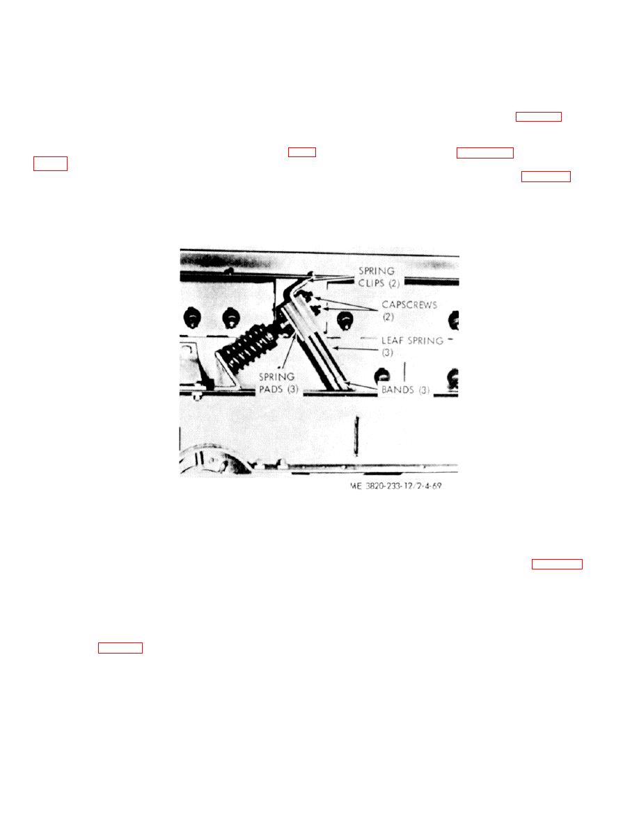
(3) Remove spring sets and pads (fig. 4-69).
other than the correct original assembly.
b. Inspection. Inspect for broken or damaged
a. Removal.
parts.
(1) Disassemble coil spring as directed in para
c. Installation. Refer to figure 4-69 and spring support
in reverse order of removal.
NOTE
(4) Adjust coil spring as directed in para 4-66.
Disassemble only one support spring group at
NOTE
time and replace on the screen assembly
Under no circumstances, mount more than a
before removing another group so that the
total of four sets of springs on any one bracket.
screen box and vibrator unit will be amply
Figure 4-69. Support sprig, removal and installation.
(1) Shut down the crusher screening unit.
4-69. Roll Crusher Discharge Opening
(2) Release the tension spring by turning the
a. General. The crusher discharge opening is the
spring adjusting bolts in a clockwise position (para 4-70).
closest distance between the two roll shell faces and
(3) Pry roll shells apart with bars or drive wedges
generally should be set approximately 1/8" less than the
between the rolls.
desired finish size product desired.
When using a
(4) Insert or remove shims for required opening.
corrugated shell it may be necessary to close the crusher
Make sure that each side has the same number and
1/8%" less than the finish size needed.
thickness of shims.
b. Adjustment. The size of the discharge opening is
NOTE
changed by inserting or removing shims which spread or
close the roll (fig. 4-70).
Always replace bolts through shims after
removing or adding shims.
4-54
